Post
Controlling Servo Motors - GUI
Controlling Servo Motors
Problem
You want to use a Raspberry Pi to control the position of a servo motor.
Solution
Use PWM to control the width of pulses to a servo motor to change its angle. Although this will work, the PWM generated is not completely stable, so there will be a little bit of jitter with the servo.
You should also power the servo from a separate 5V power supply because peaks in the load current are likely to crash or overload the Raspberry Pi.
To make this recipe, you will need:
-
5V servo motor (see “Miscellaneous”)
-
Breadboard and jumper wires (see “Prototyping Equipment”)
-
1kΩ resistor (see “Resistors and Capacitors”)
-
5V 1A power supply or 4.8V battery pack (see “Miscellaneous”)
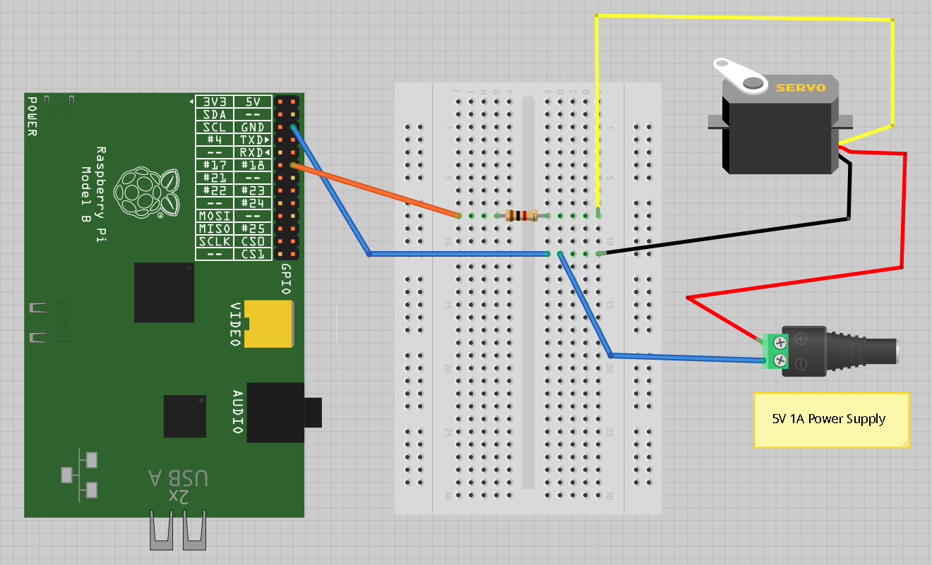
The breadboard layout for this is shown in Figure 5-1.

The 1kΩ resistor is not essential, but it does protect the GPIO pin from unexpectedly high currents in the control signal, which could occur if a fault developed on the servo.
The leads of the servo may not be the same as the colors indicated in Figure 5-2. It is common for the 5V wire to be red, the ground brown, and the control lead orange.
You can, if you prefer, power the servo from a battery pack rather than a power supply. Using a four-cell AA battery holder with rechargeable batteries will provide around 4.8V and work well with a servo. Using four alkali AA cells to provide 6V will be fine for many servos, but check the datasheet of your servo to make sure it is OK with 6V.
The user interface for setting the angle of the servo is based on the gui_slider.py program intended for controlling the brightness of an LED (“Controlling the Brightness of an LED”). However, you can modify it so that the slider sets the angle, between 0 and 180 degrees (Figure 5-2).

Open an editor (nano or IDLE) and paste in the following code. As with all the program examples in this book, you can also download the program from the Code section of the Raspberry Pi Cookbook website, where it is called servo.py.
Note that this program uses a graphical user interface, so you cannot run it from SSH.
You must run it from the windowing environment on the Pi itself or via remote control using VNC (“Controlling the Pi Remotely with VNC”). You also need to run it as superuser, so run it with the command sudo python servo.py:
fromTkinterimport*importRPi.GPIOasGPIOimporttimeGPIO.setmode(GPIO.BCM)GPIO.setup(18,GPIO.OUT)pwm=GPIO.PWM(18,100)pwm.start(5)classApp:def__init__(self,master):frame=Frame(master)frame.pack()scale=Scale(frame,from_=0,to=180,orient=HORIZONTAL,command=self.update)scale.grid(row=0)defupdate(self,angle):duty=float(angle)/10.0+2.5pwm.ChangeDutyCycle(duty)root=Tk()root.wm_title('Servo Control')app=App(root)root.geometry("200x50+0+0")root.mainloop()
Discussion
Servo motors are used in remote control vehicles and robotics. Most servo motors are not continuous; that is, they cannot rotate all the way around but rather just over an angle of about 180 degrees.
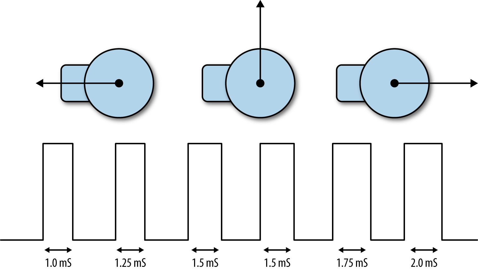
The position of the servo motor is set by the length of a pulse. The servo expects to receive a pulse at least every 20 milliseconds. If that pulse is high for 1 millisecond, the servo angle will be zero; if it is 1.5 milliseconds, it will be at its center position; and if it is 2 milliseconds, it will be at 180 degrees (Figure 5-3).

The example program sets the PWM frequency to 100 Hz, which will send a pulse to the servo every 10 milliseconds. The angle is converted into a duty cycle between 0 and 100. This actually produces pulses shorter than the 1 millisecond expected minimum value and longer than 2 milliseconds maximum.
See Also
If you have a lot of servos to control, or require greater stability and precision, then you can use a dedicated servo controller module, as described in “Controlling a Large Number of Servo Motors”.
Adafruit has developed another method of servo control.
For more information on using a breadboard and jumper wires with the Raspberry Pi, see “Using a Breadboard with Jumper Leads”.
long map(long x, long in_min, long in_max, long out_min, long out_max) { return (x - in_min) * (out_max - out_min) / (in_max - in_min) + out_min; }