Post
Building a WiFi Gateway using ESP8266
Building a WiFi Gateway using ESP8266
It's possible to build a WIFI enabled gateway running directly on an ESP8266 module.
The easiest build option is probably to use the NodeMcu Devkit v.10 (by the NodeMcu Team). Schematics and layout can be found here. This board has the ESP-12 module mounted. Just connect the radio, install gateway software and you're good to go.
Installing Gateway Software
The standard ESP8266 Gateway sketch can be used without modification (except for SSID & password).
Setting things up
- Install Arduino IDE 1.6.5+
- Add support for ESP8266 to Arduino, see Installing with Boards Manager
- Install the latest MySensors library from the Library Manager.
- Install CP2102 drivers from here.
- Connect NodeMCU board.
Compiling and uploading the gateway sketch
- Open the WiFi gateway in the Arduino IDE (File -> Sketchbook -> Libraries -> MySensors -> Esp8266Gateway
- Save it, to allow editing
- Enter your SSID and WiFi password in the 'ssid' and 'pass' variables
- Select the ESP8266 board you're targeting in Tools -> Board. Use an ESP12 module, which is a 'NodeMCU 1.0 (ESP 12E module)' board target.
- Verify your sketch. It should compile without errors.
- Now upload the sketch. This NodeMCU board normally can be flashed automatically and shouldn't need bootload/reset buttons to be pressed. If you see error, try changing baudrate from from 9600 to 57600. Still problems? Hold flash and press reset. Start upload in IDE while keeping flash-button pressed until upload starts.
- Open the serial console and watch the board connecting to your WiFi network.
- Note the IP address assigned to it. Optionally, enable a static ip in your DHCP server if you prefer to keep same ip at the next startup.
- Any application capable of communicating with the regular MySensors Ethernet gateway should be able to communicate with the ESP Gateway
- Enjoy!
To verify things you can connect a telnet session (e.g. putty) to the IP address mentioned in the serial output, port 5003 and send some serial commands!
Additional Configuration
Inclusion Mode Button
Inclusion mode, is a feature which allows you to inform the controller that you want to add new devices during a short period (60 seconds default) by pressing a physical button on your gateway. Note: This function might not be supported by all the MySensors compatible controllers. To enable this feature in your gateway, set the following defines in your sketch before including MySensors.h.
// Enabled inclusion mode feature
#define MY_INCLUSION_MODE_FEATURE
// Enables inclusion-mode button feature on the gateway device
#define MY_INCLUSION_BUTTON_FEATURE
// Set which pin you have the inclusion button attached to
#define MY_INCLUSION_MODE_BUTTON_PIN 3
// Set inclusion mode duration (in seconds)
#define MY_INCLUSION_MODE_DURATION 60
Connect the push-button momentary-switch between GND and digital pin 3.
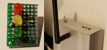
Radio Traffic LEDs
We support three LED feedback signals for radio activity - Read, Transmit, and Error. The Transmit LED is also used to provide visual feedback during active inclusion mode.
| Led color | Arduino Digital Pin | Function |
|---|---|---|
| Green | 6 | Read/RX |
| Yellow | 5 | Transmit/TX |
| Red | 4 | Error/Err |
A good choice would be either a 2 or 3 mm green/yellow/red LEDs. You will also need 3 resistors in the range 270R-510R.
Each LED is connected by its anode (long leg) to +5V. The cathode (short leg) is connected through a resistor to one of the following digital pins of the Arduino:
To enable this feature, set the following defines in your sketch before including MySensors.h.
// Set blinking period (in milliseconds)
#define MY_DEFAULT_LED_BLINK_PERIOD 300

#define MY_DEFAULT_ERR_LED_PIN 4
#define MY_DEFAULT_TX_LED_PIN 5
#define MY_DEFAULT_RX_LED_PIN 6
ESP8266Gateway Example
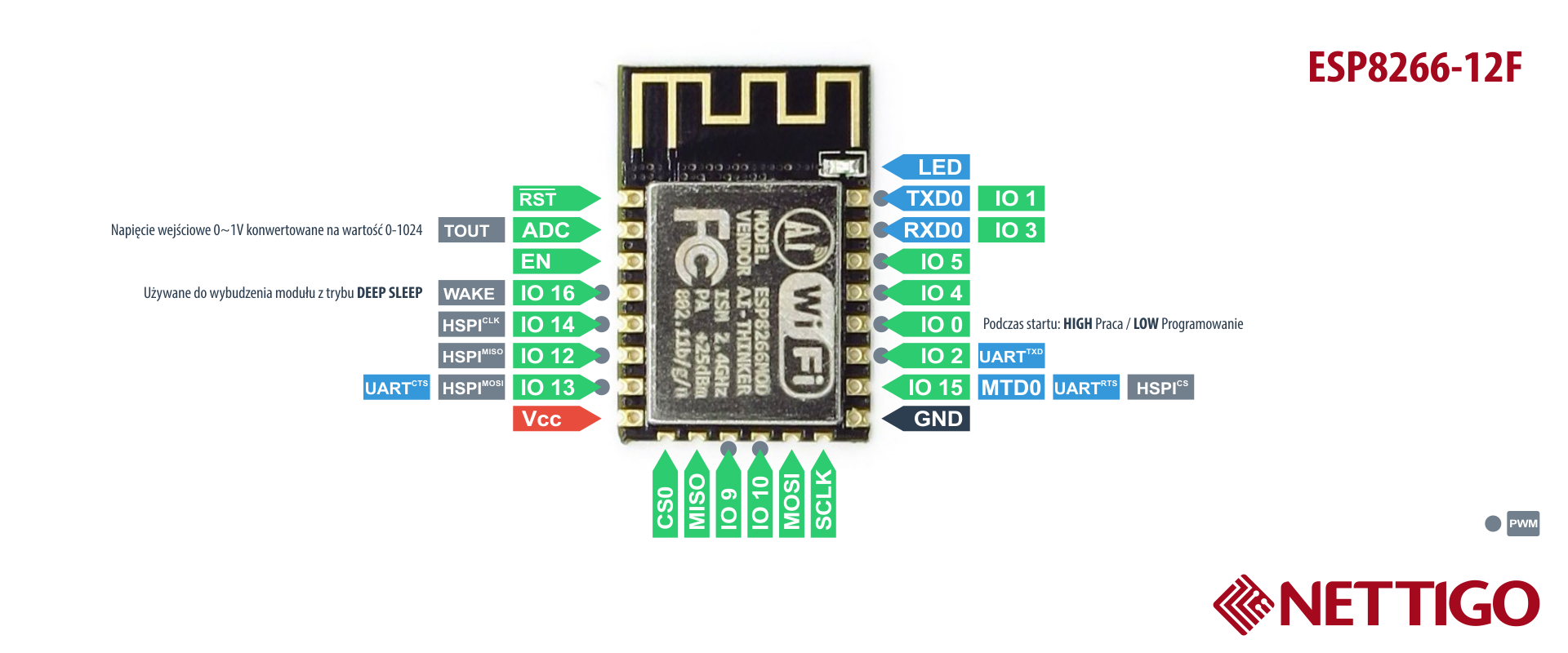
- nRF24L01+ --> ESP8266
- VCC --> VCC
- CE --> GPIO4
- CSN/CS --> GPIO15
- SCK --> GPIO14
- MISO --> GPIO12
- MOSI --> GPIO13
- GND --> GND